Hardware Installation
Pinout
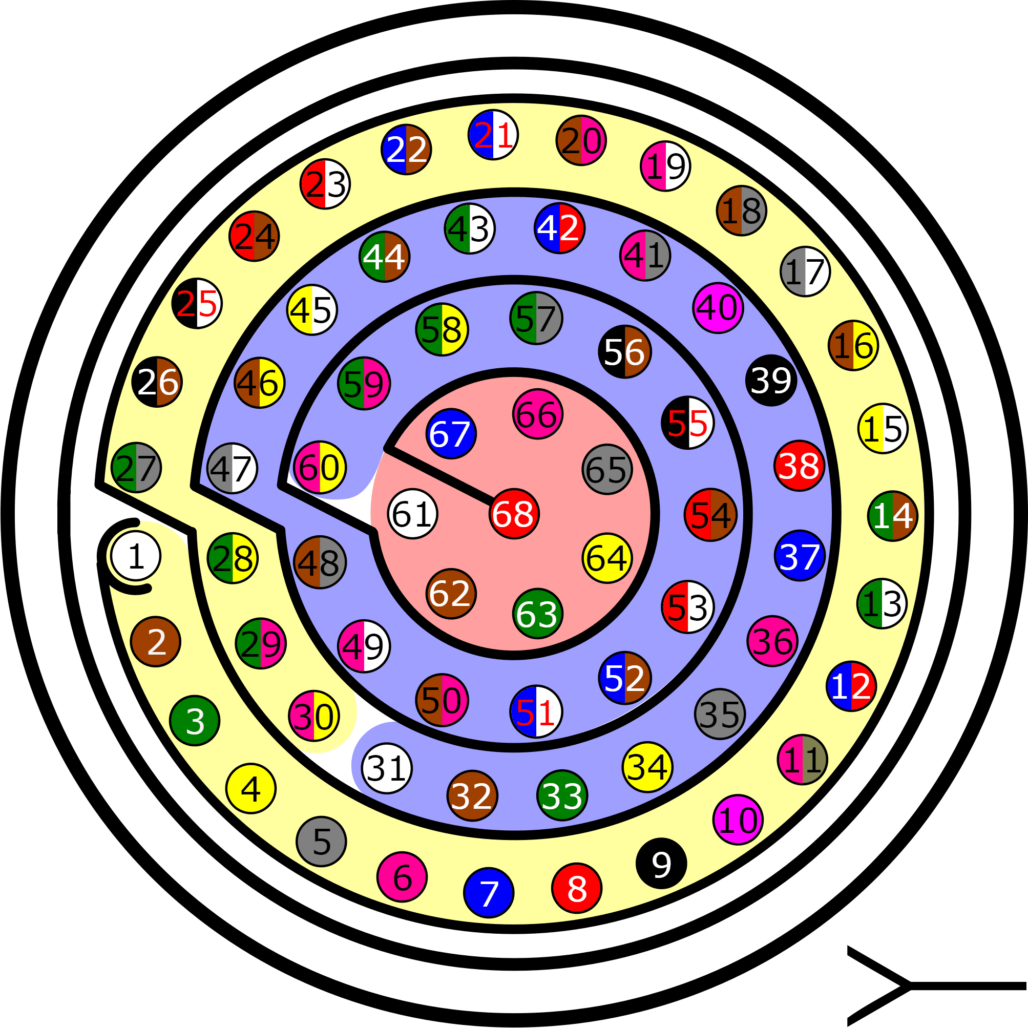
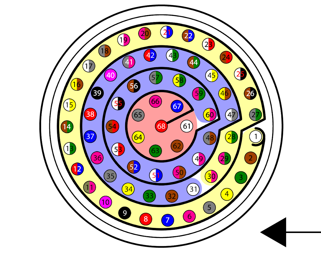
The 68 pin main connector has the distribution of input/output channels as follows:
Warning
Check the pin number before connecting. The color code is repeated 3 times due to the amount of pins. First section corresponds to pins 1-30, the second section to pins 31-60 and the third one to pins 61-68. Pin number increases following the black line of the pictures above: counterclockwise for the connector and clockwise for the plug.
| PIN | Signal | Color Code | Description |
|---|---|---|---|
| 1 | Power supply 1 | White | Power supply for the main system, redundant with Power supply 2 |
| 2 | Power supply 2 | Brown | Power supply for the main system, redundant with Power supply 1 |
| 3 | GND | Green | Ground for supply |
| 4 | GND | Yellow | Ground for supply |
| 5 | CAN (A) P | Gray | CAN bus interface. Supports data rates up to 1 Mbps, twisted pair with 120 Ω Zo recommended |
| 6 | CAN (A) N | Pink | |
| 7 | CAN GND | Blue | Ground for CAN busses |
| 8 | CAN (B) P | Red | CAN bus interface. Supports data rates up to 1 Mbps, twisted pair with 120 Ω Zo recommended |
| 9 | CAN (B) N | Black | |
| 10 | OUT RS-485 (P) | Violet | Non-inverted output from RS-485 bus |
| 11 | OUT RS-485 (N) | Gray - Pink | Inverted output from RS-485 bus |
| 12 | IN RS-485 (N) | Red - Blue | Inverted input to RS-485 bus |
| 13 | IN RS-485 (P) | White - Green | Non-inverted input to RS-485 bus |
| 14 | RS-485 GND | Brown - Green | Ground for RS-485 |
| 15 | RS-232 (A) TX | White - Yellow | RS-232 A Output |
| 16 | RS-232 (A) RX | Yellow - Brown | RS-232 A Input |
| 17 | GND | White - Gray | Ground for digital busses |
| 18 | RS-232 (B) TX | Gray - Brown | RS-232 B Output |
| 19 | RS-232 (B) RX | White - Pink | RS-232 B Input |
| 20 | I2C SCL | Pink - Brown | Clock line for I2C bus |
| 21 | I2C SDA | White - Blue | Data line for I2C bus |
| 22 | 3.3V Output | Brown - Blue | 3.3V-100 mA power supply |
| 23 | GND | White - Red | Ground for power supply |
| 24 | 5V Output | Brown - Red | 5V - 100 mA power supply |
| 25 | GND | White - Black | Ground for power supply |
| 26 | ATX (0) N | Brown - Black | ARINC 429 inverted output Port 0 |
| 27 | ATX (0) P | Gray - Green | ARINC 429 non-inverted output Port 0 |
| 28 | ARX (0) P | Yellow - Green | ARINC 429 non-inverted input Port 0 |
| 29 | ARX (0) N | Pink - Green | ARINC 429 inverted input Port 0 |
| 30 | ECAP 0 | Yellow - Pink | Encoder quadrature input |
| 31 | ECAP 1 | White | Encoder quadrature input |
| 32 | ECAP 2 | Brown | Encoder quadrature input |
| 33 | ECAP 3 | Green | Encoder quadrature input |
| 34 | PWM 0 | Yellow | PWM/DIGITAL output / DIGITAL input signal (0-5V) Warning Each pin withstands a maximum current of 8 mA |
| 35 | PWM 1 | Gray | |
| 36 | PWM 2 | Pink | |
| 37 | PWM 3 | Blue | |
| 38 | PWM 4 | Red | |
| 39 | PWM 5 | Black | |
| 40 | PWM 6 | Violet | |
| 41 | PWM 7 | Gray - Pink | |
| 42 | GND | Red - Blue | Ground for digital/analog signals |
| 43 | ANALOG (0) 3.3V | White - Green | Analog input 0-3.3 V |
| 44 | ANALOG (1) 3.3V | Brown - Green | Analog input 0-3.3 V |
| 45 | ANALOG (2) 5V | White - Yellow | Analog input 0-5 V |
| 46 | ANALOG (3) 5V | Yellow - Brown | Analog input 0-5 V |
| 47 | ANALOG (4) 12V | White - Gray | Analog input 0-12 V |
| 48 | ANALOG (5) 12V | Gray - Brown | Analog input 0-12 V |
| 49 | ANALOG (6) 36V | White - Pink | Analog input 0-36 V |
| 50 | ANALOG (7) 36V | Pink - Brown | Analog input 0-36 V |
| 51 | GND | White - Blue | Ground for digital/analog signals |
| 52 | ARX (1) P | Brown - Blue | ARINC 429 non-inverted input Port 1 |
| 53 | ARX (1) N | White - Red | ARINC 429 inverted input Port 1 |
| 54 | ARX (2) P | Brown - Red | ARINC 429 non-inverted input Port 2 |
| 55 | ARX (2) N | White - Black | ARINC 429 inverted input Port 2 |
| 56 | ARX (3) P | Brown - Black | ARINC 429 non-inverted input Port 3 |
| 57 | ARX (3) N | Gray - Green | ARINC 429 inverted input Port 3 |
| 58 | ARX (4) P | Yellow - Green | ARINC 429 non-inverted input Port 4 |
| 59 | ARX (4) N | Pink - Green | ARINC 429 inverted input Port 4 |
| 60 | GPIO 8 | Yellow - Pink | DIGITAL output / DIGITAL input signal (0-3.3V) Warning Each pin withstands a maximum current of 1.65 mA |
| 61 | GPIO 9 | White | |
| 62 | GPIO 10 | Brown | |
| 63 | GPIO 11 | Green | |
| 64 | GPIO 12 | Yellow | |
| 65 | GPIO 13 | Gray | |
| 66 | GPIO 14 | Pink | |
| 67 | GPIO 15 | Blue | |
| 68 | GPIO 16 | Red |
Harness
A wire harness is a structured assembly of cables and connectors used to organize and manage wiring in electrical and electronic systems. It is designed to ensure a tidy and secure installation of cables, preventing tangles, electromagnetic interference, and facilitating maintenance.
CEX 2.0 has two compatible harnesses:
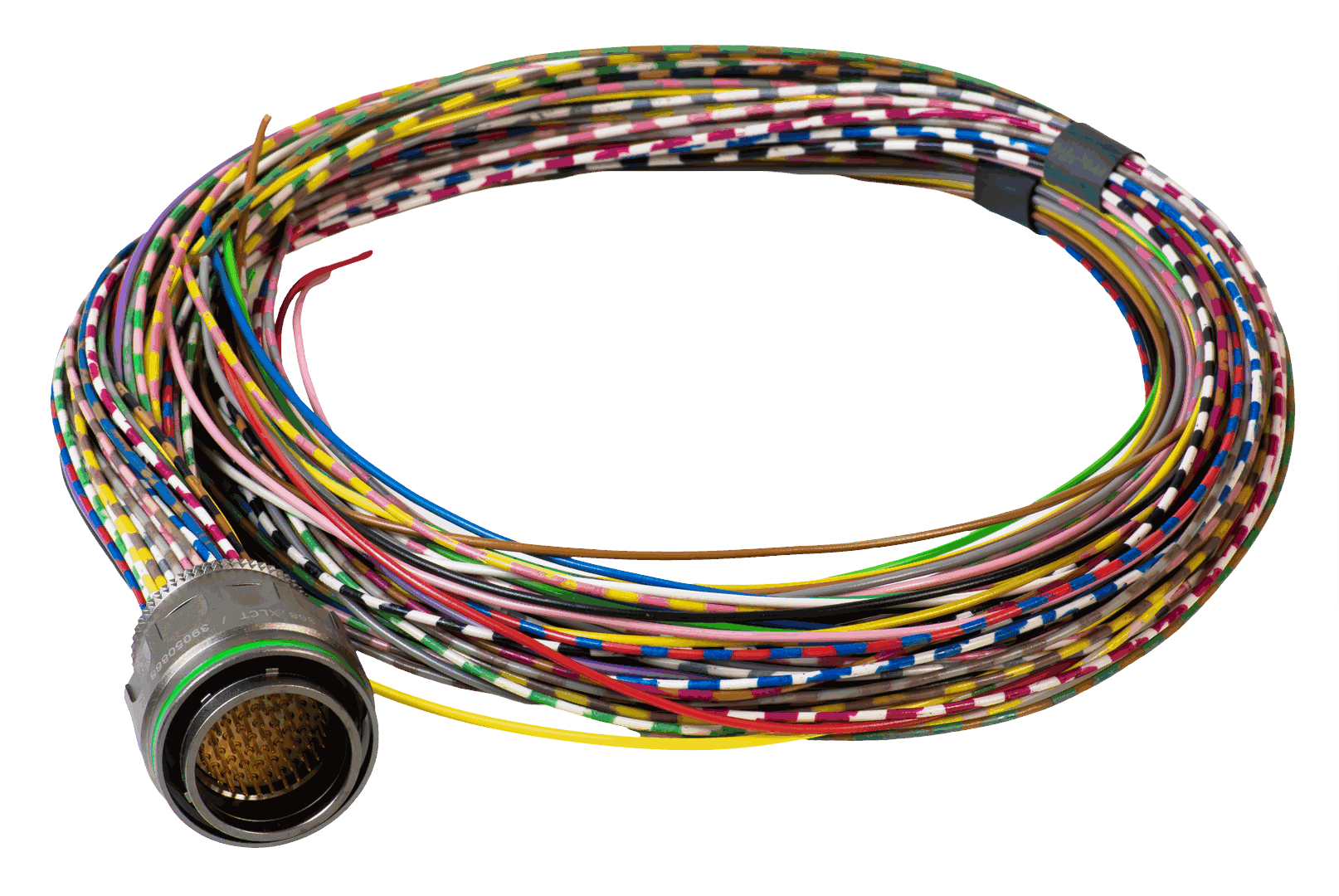
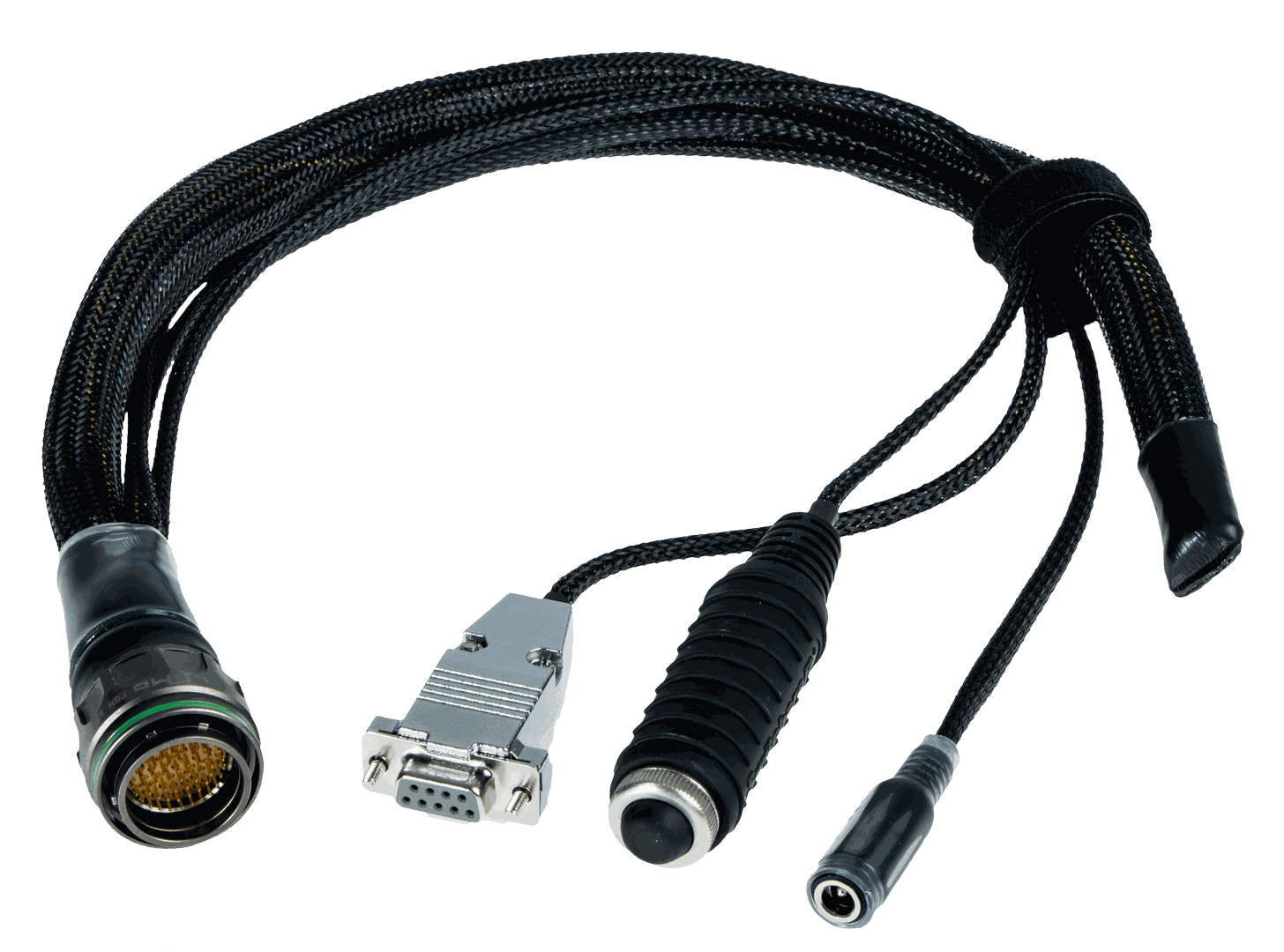
| Veronte Harness Green 68P | Dev Harness CEX 2.0 |
|---|---|
|
|
| Harness available on demand with the Embention reference P001623 | Harness available on demand with the Embention reference P006140 |
Dimensions
-
Harness Green 68P wire gauge: 22 AWG
-
Cables length: 52 cm
-
Harness plug dimensions:
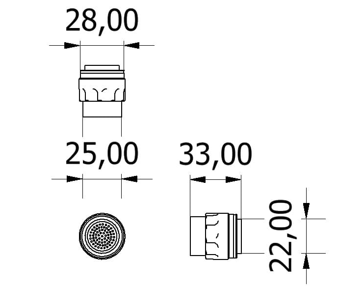
Pinout
Veronte Harness Green 68P
The pinout of this harness is the same as the Veronte CEX pinout above. The color code of the harness wires is given below.
Warning
Check the pin number before connecting. The color code is repeated 3 times due to the amount of pins. First section (yellow) corresponds to pins 1-30, the second section (blue) to pins 31-60 and the third one (red) to pins 61-68. Pin number increases following the black line of the pictures above: counterclockwise for the connector and clockwise for the plug.
| PIN | Color code | PIN | Color code |
|---|---|---|---|
| 1 | White | 35 | Gray |
| 2 | Brown | 36 | Pink |
| 3 | Green | 37 | Blue |
| 4 | Yellow | 38 | Red |
| 5 | Gray | 39 | Black |
| 6 | Pink | 40 | Violet |
| 7 | Blue | 41 | Gray - Pink |
| 8 | Red | 42 | Red - Blue |
| 9 | Black | 43 | White - Green |
| 10 | Violet | 44 | Brown - Green |
| 11 | Gray - Pink | 45 | White - Yellow |
| 12 | Red - Blue | 46 | Yellow - Brown |
| 13 | White - Green | 47 | White - Gray |
| 14 | Brown - Green | 48 | Gray - Brown |
| 15 | White - Yellow | 49 | White - Pink |
| 16 | Yellow - Brown | 50 | Pink - Brown |
| 17 | White - Gray | 51 | White - Blue |
| 18 | Gray - Brown | 52 | Brown - Blue |
Dev Harness CEX 2.0
This harness has some connectors already implemented for easy operation. Below is detailed information on which pins these connectors are connected to:
| Connector | PIN | Signal |
|---|---|---|
| Main VCC | 1 | Power supply 1 |
| 2 | Power supply 2 | |
| 3 | GND | |
| 4 | GND | |
| RS232 connector | 15 | RS-232 (A) TX |
| 16 | RS-232 (A) RX | |
| 17 | GND | |
| Maintenance button | 20 | I2C SCL |
| 21 | I2C SDA |
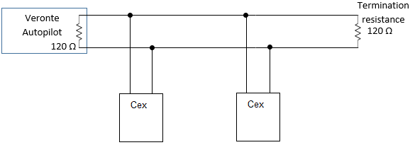
CAN Assembly
As described in Warnings section, CEX itself does not allow the connection of multiple CEX or other CAN Bus devices to the same line. It is therefore possible to use a Veronte Autopilot for this purpose. Considering Veronte Autopilot includes one entrance resistance of 120 , a second resistance needs to be placed at the end of the line (again 120 ). This resistance may be placed on the cable or on another PCB.
© 2025 Embention. All rights reserved.